|
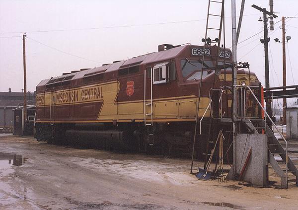
Here is the WC 6652, an FP-45, sitting on the Sanding track, just outside the roundhouse. Sometime I'll have to find a better picture without any obstructions.
|
|
|
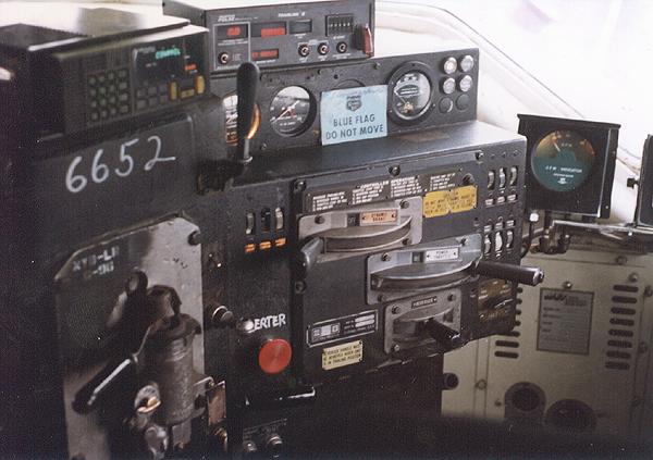
Here is the control stand. The levers are: starting on the left console (from top to bottom) is the Horn (the highest handle next to the radio), Automatic brake, then the independent brake (the handle is just under the red alerter button), the three on the center console is (from top to bottom) dynamic brake, throttle, and the reverser.
|
|
|
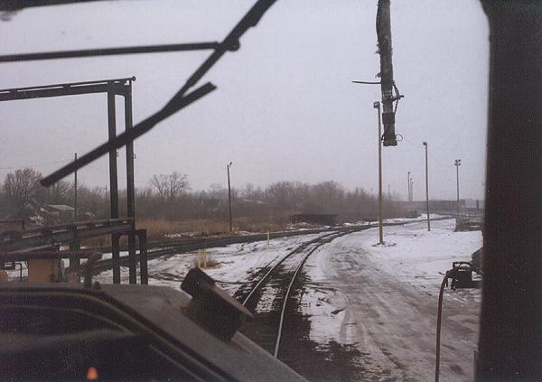
This is the view from the engineers seat. The speedometer is just under the "V" of the window.
|
|
|
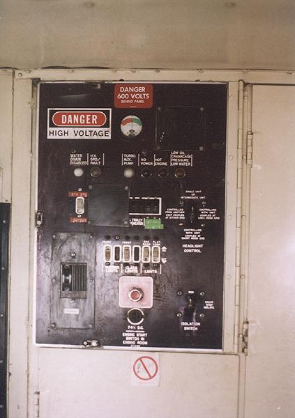
This is one of the circuit breaker panels, which is on the back wall behind the controller and brake stand. This panel also has indicator lamps which light should certain conditions exist. There is another panel along with the battery switch in the door under this panel.
In a little more detail, the gauge on top shows battery charge/discharge current. The indicator lamps under that are as follows: (from left to right) "Water drain disabled", should the water temp drop below 32 degrees, the engine will self drain; "High Voltage Ground Fault", will light should any part of the high voltage system go to ground, this will also prevent the loco from making power; "Turbo Aux. Pump", all EMD turbocharged engines have a motor driven oil pump to supply oil to the turbocharger immediately after the engine has been shutdown. This prevents residual heat in the turbine from possibly damaging the turbo bearings. This indicator is on when this pump is on; "No Power", lights when the auxiliary generator is not making any power; "Hot Engine", lights when the engine is beyond its normal operating temperature, the engine load will automatically be reduced; "Low Oil, Crankcase Pressure, Low Water", all three of these will cause the engine to shutdown by tripping the Low Oil button on the governor. Low Oil pressure will cause the governor button to trip. There is a device called an engine protector which senses high crankcase pressure, and low water, both will also trip the low oil button on the governor. There are many other switches on this panel for lights, heaters, and other items which vary from loco to loco.
|
|
|
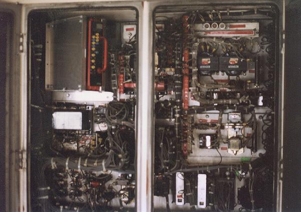
The heart of the low voltage electrical system. All these relays and interlocks and other components are part of what controls transition, direction, etc. On the other side of the wall from this panel and in the rear electrical cabinet is the high voltage cabinets, which contains the reversers, power contactors, etc.
|
|
|
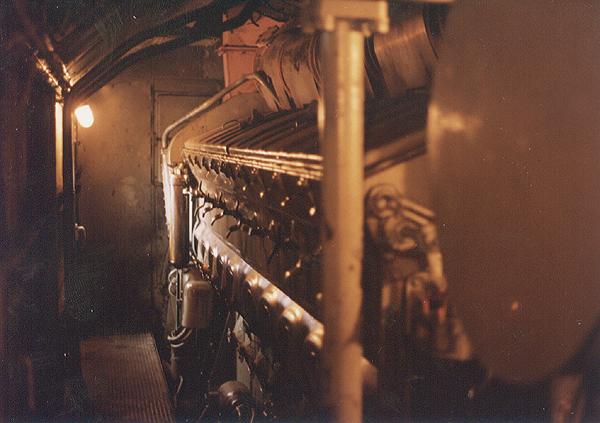
This view in the engine room is on the firemans side of the loco. The big round plate at the right of the picture is the cooling system expansion tank. The alternator and turbo are at the rear of the engine, or to the front of the loco. That may sound funny, but there is a front and rear to the diesel engine which is opposite to the front and rear of the locomotive. The governor end is designated the front of EMD engines.
|
|
|
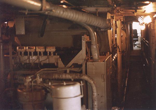
In this view on the engineers side, you can see part of the WBO air compressor and the equipment rack. The equipment rack contains the Expansion tank on top, diagonally mounted is the oil cooler, the oil filter housing, and on some engines may have the primary fuel filters.
|
|